
Daily checks (10–15 minutes)
- Verify lubrication level and delivery; check for abnormal guideway noise.
- Clean chips around covers and seals to prevent drag and stick-slip.
- Monitor spindle temperature trend; investigate unusual rises.

For large plastic molds, “size” is not the main problem—deflection, vibration, thermal drift, and motion ripple are. When a mold base grows to meters and machining time stretches to days, small structural weaknesses become visible on the surface: waviness, mismatch at parting lines, inconsistent texture, and costly hand rework. This article explains how large CNC milling machines—especially double-column (gantry) CNC milling centers—achieve stable accuracy through high-rigidity architecture and smooth, predictable transmission, and how process choices (tools, parameters, quality checks) can raise both precision and throughput in real mold shops.
Large plastic molds often require deep cavities, long overhang tools, and multi-face machining with tight tolerance stacks. In that context, the machine behaves like a “system spring”: the final surface is a result of structure + spindle + drive + control + tooling. A useful rule in production is that surface errors often correlate with dynamic stiffness, not just static accuracy.
Industry note (ISO-style thinking): In long-cycle machining, repeatability is frequently impacted more by thermal balance and vibration behavior than by nominal positioning specs. Many mold shops therefore evaluate machines with test cuts and stability checks, not spec sheets alone.
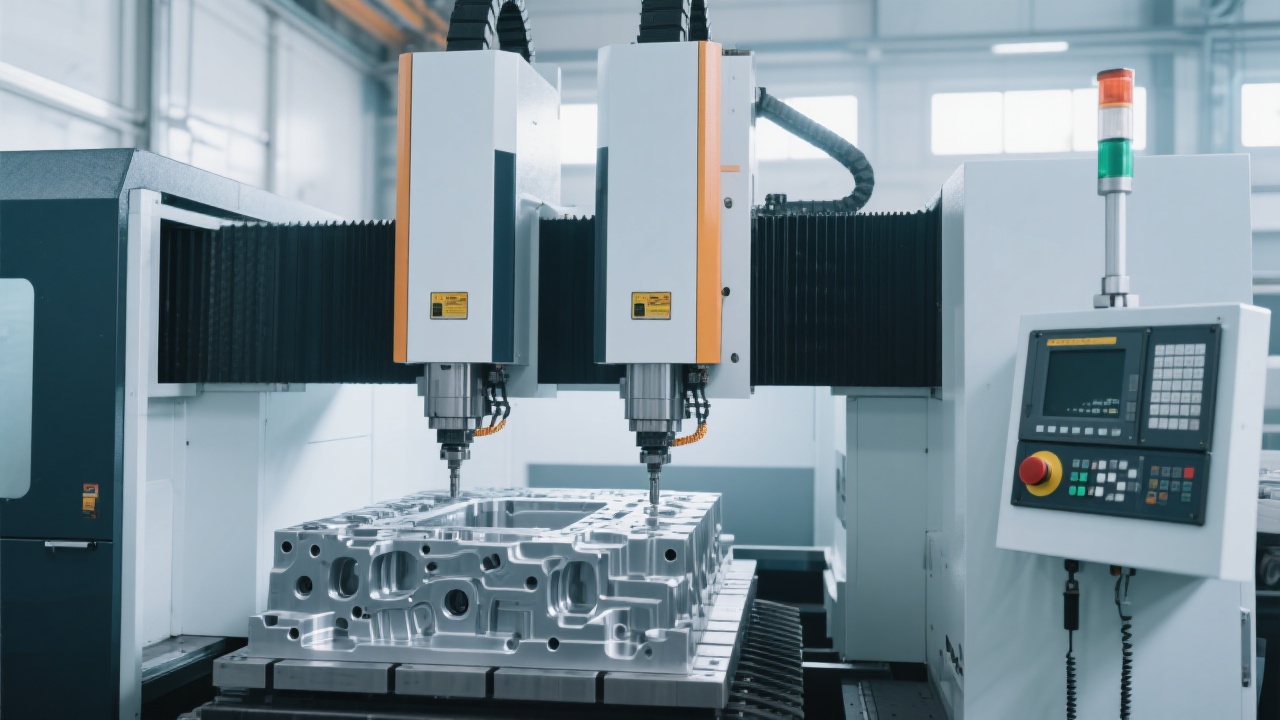
In large-format mold cutting, the most practical rigidity improvements come from a balanced combination of structural geometry, joint stiffness, and mass distribution. A double-column design can reduce long-span bending and keep the cutting force loop short—critical when roughing large blocks or finishing wide surfaces.
Column–beam stiffness & symmetry: symmetrical load paths reduce twist under heavy cuts; wide column spacing improves yaw resistance.
Guideway type & preload strategy: proper preload supports damping and reduces micro-chatter during finishing, especially with long-reach tools.
Joint rigidity (bolted interfaces): interface design and torque consistency often decide real stiffness more than casting thickness.
Thermal stability design: consistent warm-up, balanced cooling, and predictable thermal growth minimize “drift-shaped” errors on large plates.
Actual targets depend on mold size, material, and tolerance class, but many shops consider the following as realistic operational references for well-tuned large CNC milling:
| Item | Typical shop reference | Why it matters |
|---|---|---|
| Finish allowance before final pass | 0.2–0.5 mm (large surfaces) | Stabilizes cutting forces and reduces spring-back variation. |
| Ball end step-over (finishing) | 6–12% of tool diameter | Balances scallop height vs. cycle time. |
| Long-cycle drift control window | ±0.01–0.03 mm over several hours (process-dependent) | Keeps parting surfaces and alignment consistent. |
| Typical rough-to-finish time savings after stabilization | 8–15% (case-dependent) | Less rework, fewer semi-finish repeats, more predictable programs. |
For large molds, a “powerful” axis drive is not enough. The machine must move with low ripple, stable servo response, and consistent backlash behavior across the full travel. When motion is smooth, the cutter engagement becomes stable—finishing improves and tool life becomes more predictable.
Practical test used by many mold teams: run a long-axis constant feed finishing path on a flat reference plate and check for repeating surface bands. If the band spacing matches a drive component pitch (screw pitch or gearbox cycle), the root cause is typically in transmission or servo ripple—not tooling.
Large plastic molds demand long strokes on X/Y and often a tall Z envelope for deep cavities. The longer the travel, the more the process must consider straightness, pitch/yaw control, and thermal gradient. Even when positioning is accurate at a single point, the real challenge is consistency over the full working area.
A rigid, stable machine is a foundation; the rest is process discipline. Large mold cutting is best managed as a sequence of “risk reductions,” where each stage removes uncertainty for the next. The goal is to finish with minimal benchwork while protecting the tool, spindle, and geometry.
Roughing (high material removal, stable engagement) → Semi-finishing (uniform allowance, remove waviness) → Finishing (surface integrity, low ripple) → Verification (probing/CMM checkpoints) → Spot correction (local rework only)
While exact settings depend on material grade and tool supplier recommendations, many mold shops follow these patterns to improve stability:
Quality gate that prevents expensive rework: after semi-finishing, probe key planes/bores and compare to CAD allowance map. Catching a 0.05 mm mismatch early can save hours of hand fitting on parting surfaces later.
In a typical large mold manufacturing scenario (automotive interior or large appliance shells), a gantry-style CNC milling center is used to complete facing, cavity roughing, semi-finishing, and final surface passes on a multi-meter mold base. When rigidity and transmission stability are properly managed, shops often report:
In practice, many mold shops see overall throughput gains in the 8–15% range once they standardize toolpaths, stabilize thermal routines, and tighten maintenance. The most valuable gain is not only speed—it’s the ability to run long programs with fewer surprises.
Large CNC milling machines work under heavy inertia and long stroke conditions, so small maintenance gaps can quickly show up as surface defects or positioning inconsistency. A disciplined routine helps keep accuracy stable and extends component life.
Many teams troubleshoot in this order: tool wear → tool holding/runout → spindle condition → transmission ripple → servo tuning. This sequence prevents over-adjusting the machine when the root cause is actually tooling or holding.
For shops balancing heavy roughing and refined finishing, spindle interface selection becomes part of the overall solution. 凯博数控 supports configurations where users can match rigidity and tool ecosystem needs—such as choosing between BT40 and BT50 spindle options—based on mold size, cutter diameter, and target removal rate.
Compare application fit for roughing torque, tool availability, and finishing stability—aligned with real mold shop workflows.
View BT40 & BT50 Spindle ConfigurationsTip for technical evaluation: ask for representative test-cut conditions (material, tool overhang, surface spec) so the results translate to your mold programs.

 148
|
148
|
 High-speed CNC milling machine
Heavy-cutting machining center
Intelligent CNC technology
Automated machining equipment
Manufacturing innovative technology
High-speed CNC milling machine
Heavy-cutting machining center
Intelligent CNC technology
Automated machining equipment
Manufacturing innovative technology
 484
|
composite CNC milling machine
large CNC milling machine
GV1625 milling equipment
aerospace composite machining
precision large-part machining
316
|
GV1625 dual-column CNC milling machine
large complex part machining
rigid steel structure
machining efficiency improvement
aerospace component manufacturing
340
|
GV6050 CNC milling center
high-speed heavy cutting
efficient milling
milling time reduction
hard material machining
382
|
High-speed CNC milling machine
GV6050 application case
Cost reduction and efficiency improvement in intelligent manufacturing
Double-column vertical machining center
CNC machine cost optimization
484
|
composite CNC milling machine
large CNC milling machine
GV1625 milling equipment
aerospace composite machining
precision large-part machining
316
|
GV1625 dual-column CNC milling machine
large complex part machining
rigid steel structure
machining efficiency improvement
aerospace component manufacturing
340
|
GV6050 CNC milling center
high-speed heavy cutting
efficient milling
milling time reduction
hard material machining
382
|
High-speed CNC milling machine
GV6050 application case
Cost reduction and efficiency improvement in intelligent manufacturing
Double-column vertical machining center
CNC machine cost optimization