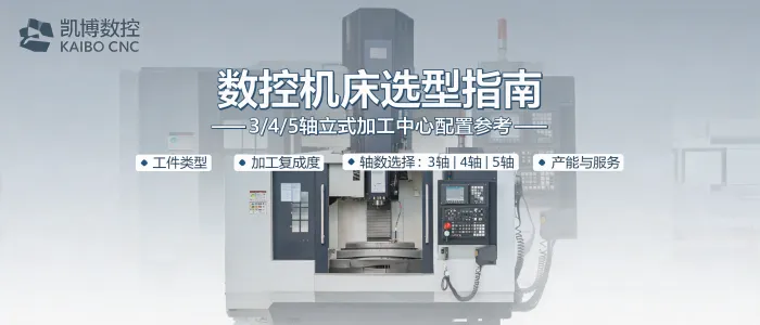
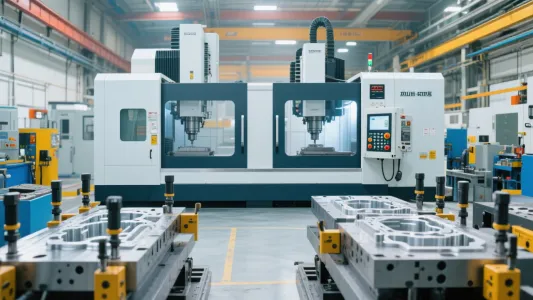
A vertical machining center (VMC) is a CNC machine tool with a vertically oriented spindle, commonly used for milling, drilling, boring, tapping, and other precision machining operations. For manufacturers, the practical difference between a 3-axis, 4-axis, or 5-axis vertical machining center lies in how many controlled movements are available and how efficiently the machine can reach the required surfaces of a part.
Kaibo CNC develops and manufactures 3-axis, 4-axis, and 5-axis vertical machining centers to support different part geometries, production requirements, and CNC machine selection considerations. The right configuration should be determined by the workpiece, machining features, tolerances, batch size, and preferred setup strategy.
In a typical vertical machining center, the cutting tool is held in a spindle positioned above the worktable. CNC control coordinates the movement of the spindle or table along linear axes, allowing the tool to remove material according to a programmed toolpath. Depending on the machine configuration, additional rotary movement can be introduced to present more sides or angled surfaces of the workpiece to the cutting tool.
A VMC is widely considered when a production task requires repeatable machining of prismatic parts, plates, housings, molds, fixtures, and components with multiple holes, pockets, profiles, or contoured features. The machine’s usable capability is not defined by axis count alone; tooling, fixturing, workholding, programming, material, and process planning also influence the final machining result.
In CNC machining, an “axis” refers to a controlled direction of movement. A standard 3-axis vertical machining center uses three linear axes:
A 4-axis or 5-axis machining center adds one or two rotary axes. These rotary movements can rotate or tilt the workpiece, or in some configurations support movement through a rotating and tilting spindle head. The specific kinematic arrangement depends on the machine design.
| Configuration | Controlled Movement | Typical Machining Access | Selection Consideration |
|---|---|---|---|
| 3-axis VMC | X, Y and Z linear movement | Top surfaces and features accessible through repositioning or multiple setups | A practical option for parts with primarily planar or vertical features |
| 4-axis VMC | Three linear axes plus one rotary axis | Multiple sides or circumferential features can be indexed or machined with rotary positioning | Useful where reducing manual repositioning can improve workflow consistency |
| 5-axis VMC | Three linear axes plus two rotary axes | Complex angled, contoured, and multi-face surfaces may be accessed with fewer workpiece changes | Appropriate for more complex geometries and processes requiring broader tool access |
The actual machining approach depends on the part design and machine configuration. Rotary axes may be used for indexing between positions or for coordinated machining, according to process requirements and programming strategy.
A 3-axis machining center controls the cutting process through X, Y, and Z linear movement. The workpiece is generally fixed in one orientation during a machining cycle. When additional faces need processing, operators may reposition the part manually or use dedicated fixtures to establish a new setup.
A 4-axis vertical machining center adds a rotary axis to the three linear axes. This added movement enables the workpiece to be rotated to different positions, giving the cutting tool access to multiple faces without requiring the same level of manual refixturing as a basic 3-axis process.
For example, a rotary axis can support machining around the perimeter of a component or indexing a part to defined angular positions. This can be valuable for workpieces with repeated features around a circumference, features on several side faces, or processes where setup reduction is an important consideration.
A 5-axis machining center combines the three linear axes with two rotary axes. This configuration creates more positioning options between the tool and the workpiece, helping manufacturers address parts with complex curves, compound angles, deep cavities, or features distributed across several orientations.
In a 5-axis process, the additional rotary movement may be used to position the workpiece at an angle before machining or to move continuously in coordination with the linear axes. The appropriate method depends on part geometry, surface requirements, tool access, programming capability, and the overall manufacturing process.
A 5-axis machining center is not simply a higher-axis alternative. It is a configuration intended to expand accessible machining positions and support a process plan for more demanding part geometry.
CNC machine selection should begin with the part and process rather than axis count alone. A machine that matches the actual machining requirement can help create a more practical production arrangement.
Ningbo Kaibo CNC Machinery Co., Ltd. provides vertical machining center solutions across 3-axis, 4-axis, and 5-axis configurations, alongside CNC engraving and milling machines and customized CNC machine tools. With research, manufacturing, marketing, and service capabilities, Kaibo CNC supports B2B customers seeking equipment aligned with their processing tasks.
For a meaningful evaluation, prepare key workpiece information including material, dimensions, drawings, feature locations, expected production volume, and machining objectives. This provides a clearer basis for determining whether a 3-axis, 4-axis, or 5-axis vertical machining center is appropriate for the intended application.
Selecting a vertical machining center is a process of matching machine movement, workpiece access, and production planning. By defining the part-processing requirement first, manufacturing teams can compare 3-axis, 4-axis, and 5-axis CNC machines on a practical and technically relevant basis.
 241
|
241
|
 Ningbo Kaibo CNC Machinery
CNC machine selection
3/4/5-axis vertical machining center
custom CNC machine
machining requirements analysis
Ningbo Kaibo CNC Machinery
CNC machine selection
3/4/5-axis vertical machining center
custom CNC machine
machining requirements analysis
 40
|
Multi-Axis CNC Gantry Milling Machine
Automotive Component Precision Machining
Intelligent CNC System
Automated Production Line Integration
New Energy Vehicle Parts Machining
40
|
Multi-Axis CNC Gantry Milling Machine
Automotive Component Precision Machining
Intelligent CNC System
Automated Production Line Integration
New Energy Vehicle Parts Machining
 98
|
plastic mold CNC milling machine
large CNC milling machine
mold processing technology
DC1317 machine
CNC machine tool selection
98
|
plastic mold CNC milling machine
large CNC milling machine
mold processing technology
DC1317 machine
CNC machine tool selection
 129
|
Kaibo CNC
CNC machine tool supplier evaluation
machine tool manufacturing capability
after-sales service system
B2B equipment procurement
497
|
Kaibo CNC
custom CNC machine
CNC machine project process
equipment solution design
CNC equipment delivery
129
|
Kaibo CNC
CNC machine tool supplier evaluation
machine tool manufacturing capability
after-sales service system
B2B equipment procurement
497
|
Kaibo CNC
custom CNC machine
CNC machine project process
equipment solution design
CNC equipment delivery